Navigation Menu 
[expand all...]
[COLLAPSE ALL...]
|
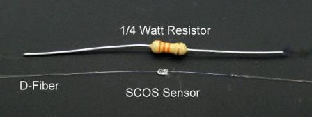
Slab Coupled Optical Sensor
SCOS
 Expand All
Compress All
Expand All
Compress All
What is a SCOS?
Basic Concept
- SCOS is an electric field detector that is made entirely of dielectric. The slab that is placed on the fiber will absorb specific frequencies of light. Under the effect of an electric field, the frequencies of light that the crystal absorbs will change. By measuring these frequencies, the strength of the electric field can be measured.
Why SCOS?
Advantages
- The sensor contains no metal so it will not disrupt the field it is detecting.
- They are very small and can easily be placed within a circuit board.
- All of the electrical equipment used to measure the field can be a long way from the sensor.
- The sensor itself is relatively cheap to make.
Disadvantages
- The fiber is fairly week and easy to break.
- The equipment needed to use a SCOS is expensive.
- While trying to make one, one can easily become frustrated.
Fabrication of a SCOS:
Etching:
- 1) Cut off about 100 cm of D-fiber
- 2) Strip the coat off both ends of the fiber and also about 2 cm in the middle of the fiber.
- 3) Place the fiber in an etch boat with the flat side facing up.
- 4) Clean all three stripped regions with isopropyl alcohol. Make sure to use a sonic cleaner on the middle region.
- 5) Take the fiber to the fume hood and align the fiber so that an untra-violet laser is shining through a polarizer, then through the fiber, then again through a polarizer that is in the same direction as the first, and finally into an optical power meter. You should be able to get at least 50 uW if not many more.
- 6) Put on the protective equipment including latex gloves, an apron, goggle, face shield, and a set of nitrial gloves.
- 7) Lower the fiber into the hydrofluoric acid until a little less than 1 cm is submersed in the HF. Make sure that none of the fiber's coating touches the HF.
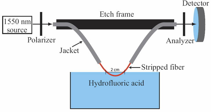
- 8) Watch the power until it has oscillated 2.5-3 times depending on how much fiber is in the HF (3 times for 1.5 cm less for less length)
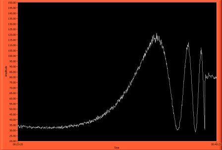
- 9) Once it has oscillated the correct number of times, immediately remove the fiber from the HF bath and place it in water. Proceed to put the HF away.
- 10) Again clean the fiber in isopropyl alcohol.
Splicing:
- 1) Use the Fujikura fusion splicer.
- For a basic tutorial of how to use this fusion splicer click here.
- 2) First prepare a PandA fiber and an E-fiber by stripping, cleaving, and cleaning them.
- 3) Put them both into the fusion splicer and line up the fibers.
- 4) When the fibers are aligned hook the end of one fiber to a laser and the end of the other fiber to a polarizer on which you can change the polarization. Hook the output of the polarizer to an optical power meter.
- 5) Rotate the polarizer and check the extinction ratio. If it is less than about 30 dB extinction, use the fusion splicer to rotate one of the fibers about 5 degrees and check again. Keep doing this until a high level of extinction is achieved.
- 6) After the fibers are aligned get them as close as you can to each other and then move the fibers to re-optimize power transfer. Then spice the fibers together.
- 7) Repeat the aligning and splicing process for splicing the E-core to D-fiber.
Applying the Slab:
- 1) Take the recently spliced fiber and align it so that an ASE source is shining into a vertically aligned polarizer into the fiber. Put the other end of the fiber into an optical power meter.
- 2) Maximize the power through the fiber and then hook the end that is currently in the optical meter into a spectrum analyzer.
- 3) Place the crystal or polymer you are using to the fiber and cover it in UV glue.
- 4) Slide the slab around until resonances start to appear. Keep sliding until the resonances are about 8 dB deep.
- 5) Cure the glue using a UV lamp.
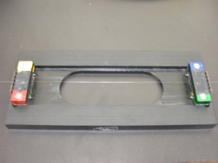
Packaging
Straight
- 1) Make sure the UV cure glue is totally dry before starting.
- 2) Place the SCOS inside a 1 mm wide glass tube.
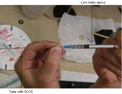
- 3) Fill the tube with low index epoxy.
- 4) Place teflon tubing on each end of the glass tube and the use heat shrink on the edges of the glass tube to create a better joint between the edge of the glass tube the teflon tubing.
Bent
- 1) Make sure the UV cure glue is totally dry before starting.
- 2) Strip a little bit more the fiber near where the slab is on the fiber.
- 3) Feed the fiber through a glass tube until the stripped region is outside of the tube but the slab is still in the tube.
- 4) Take the end of the fiber and feed it back through the glass tube so the fiber creates a loop and only the stripped region is outside of the tube.
- 5) Pull gently on the fibers on the other end of the glass tube until the loop starts providing resistance.
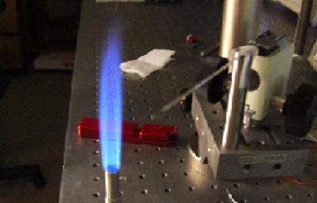
- 6) Put the end of the glass loop in the top of the flame flame generated by the Bunsen burner that is about 10 cm tall. The loop should shrink.
- 7) Pull the now smaller loop into the tube and repeat the process until the diameter of the loop is less than the width of the tube.
- 7) Fill the tube with low index epoxy.
- 8) Cover the tip of the loop with epoxy to support it and also hold it in place.
Splicing:
- Use the same technique as in the first splicing step to splice the other end of the SOCS.
Rejoicing!
- Cry out in glee as you finish! Make sure that everyone in the lab knows that you have successfully completed your SCOS project. Make sure that there is some type of refreshments on hand and throw a spontaneous party right there in the lab. The more food and drink you have on hand the better. Not only will these parties increase morale, they will also provide a much needed break from the daily grind in the lab.

|
